Figure
Description
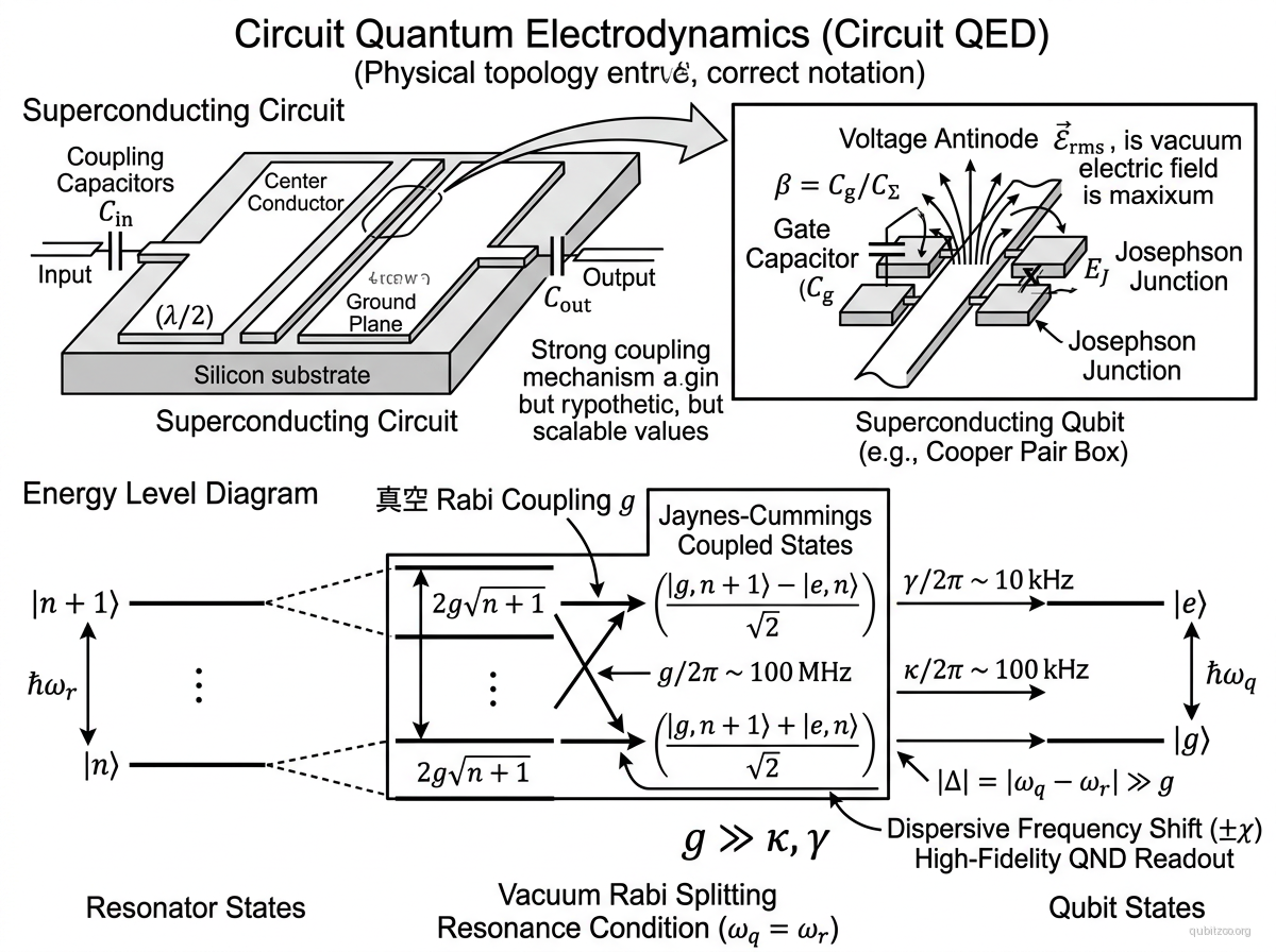
Circuit quantum electrodynamics (circuit QED) is the solid-state realization of cavity QED, where a superconducting qubit plays the role of the atom and a coplanar waveguide (CPW) transmission line resonator plays the role of the optical cavity. Proposed by Blais, Huang, Wallraff, Girvin, and Schoelkopf (2004), the key insight is that the zero-point energy of a quasi-1D resonator is concentrated in an extremely small effective volume ( cubic wavelengths), producing rms vacuum fields — about 100× larger than 3D microwave cavities. Combined with the enormous transition dipole moment of the Cooper pair box ( atomic units), this yields coupling strengths three orders of magnitude beyond atomic microwave cQED.
The system reaches the strong coupling regime where the vacuum Rabi frequency vastly exceeds both the cavity decay rate and the qubit decay rate . In the dispersive regime (), the cavity frequency shifts by depending on the qubit state, enabling quantum non-demolition (QND) readout. The resonator simultaneously provides Purcell protection — suppressing spontaneous emission by a factor — and acts as a quantum bus for entangling qubits at different antinodes via virtual photon exchange.
Circuit QED is the foundational measurement and coupling architecture underlying virtually all modern superconducting quantum processors.
Hamiltonian
At the charge degeneracy point, the system is described by the Jaynes-Cummings Hamiltonian:
where is the resonator frequency, is the qubit frequency, is the vacuum Rabi coupling, and are the resonator photon operators.
The coupling strength is:
where is the capacitive coupling ratio, is the capacitance per unit length, and is the resonator length.
In the dispersive regime (), the effective Hamiltonian becomes:
where is the dispersive shift. The qubit-state-dependent cavity frequency shift enables QND measurement of the qubit.
Motivation
Previous proposals for coupling superconducting qubits used discrete LC circuits or large Josephson junctions, which suffered from parasitic resonances and 1/f noise sensitivity. The transmission line resonator approach provides: strong inhibition of spontaneous emission (Purcell protection), high-fidelity QND readout via dispersive phase shifts, a natural quantum bus for entangling qubits separated by centimeter distances, and compatibility with standard lithographic fabrication. Circuit QED made dispersive readout and multi-qubit coupling practical, enabling the scaling of superconducting quantum processors.
Experimental Status
First strong coupling — Wallraff et al. (2004):
- Achieved strong coupling between a Cooper pair box and a CPW resonator with .
- Observed vacuum Rabi splitting in transmission spectroscopy.
Dispersive readout established:
- QND measurement of qubit state via cavity phase shift became the standard readout method for all transmon-based processors.
Quantum bus demonstrations:
- Two qubits at different antinodes entangled via virtual photon exchange with effective coupling .
3D circuit QED:
- Extension to 3D microwave cavities achieved resonator lifetimes , enabling long-lived bosonic codes.
Key Metrics
| Metric | Value | Notes | Fidelity reference |
|---|---|---|---|
| Vacuum Rabi coupling | 50–400 MHz | Depending on qubit type and geometry | — |
| Resonator | 1–10 μs (2D), >1 ms (3D) | Planar vs 3D cavity | — |
| Dispersive shift | 0.5–5 MHz | — | |
| Readout speed | 200–500 ns | Dispersive measurement | — |
| Purcell limit | >1 ms | With Purcell filter | — |
| Resonator footprint | ~5 mm (λ/2) | Coplanar waveguide | — |
| Operating temperature | 10–20 mK | Dilution refrigerator | — |
| Strong coupling ratio | 10–1000 | = resonator linewidth | — |
References
Original proposal
- A. Blais et al., “Cavity quantum electrodynamics for superconducting electrical circuits: An architecture for quantum computation,” Phys. Rev. A 69, 062320 (2004) — arXiv:cond-mat/0402216
First experimental demonstration
- A. Wallraff et al., “Strong coupling of a single photon to a superconducting qubit using circuit quantum electrodynamics,” Nature 431, 162 (2004)
Linked Papers
Evergreen context
- jaynes-cummings-in-circuits — the atom-cavity Hamiltonian in its superconducting form
- dispersive-readout-mechanism — why off-resonant coupling yields QND measurement
- resonator-as-quantum-bus — how the cavity mediates long-range qubit-qubit coupling
- vacuum-rms-field-scaling — why CPW resonators achieve unusually large zero-point fields
- purcell-protection-via-detuning — how detuning and filters suppress spontaneous emission
Related Entries
- transmon — most common qubit used in circuit QED architectures
- cooper-pair-box-charge-qubit — original qubit in the Blais et al. proposal
- fluxonium — also operates within circuit QED, requires auxiliary readout
- qubit-readout — dispersive readout is the primary application of circuit QED