 Qubit Zoo
Figure
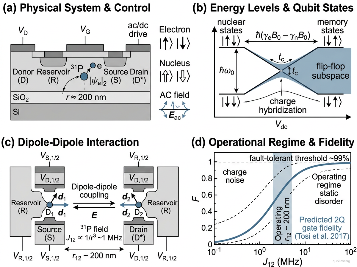
Description
The flip-flop qubit encodes quantum information in the combined electron-nuclear spin states of a phosphorus () donor atom in silicon. Using the convention adopted in the proposal and experimental demonstration, the computational basis states are:
where arrows denote electron spin () and nuclear spin () orientations. In each state, the electron and nuclear spins point in opposite directions — hence “flip-flop.” These states are connected by a simultaneous electron-nuclear spin flip driven by transverse hyperfine interaction, which can be electrically tuned by displacing the electron wavefunction relative to the nucleus using gate electrodes.
The 2017 processor proposal adds a deliberately hybridized orbital degree of freedom: a donor-bound orbital and an interface orbital . Their vertical separation creates a tunable electric dipole , and hyperfine coupling transfers that electric interaction to the flip-flop spin subspace. In the proposal, a effective coupling can be maintained for donor separations from 180 to 500 nm by retuning the donor-interface tunnel coupling. That is far less placement-sensitive than the exchange interaction used by conventional donor-spin architectures.
The first experiment, reported in 2023, demonstrated coherent electric control of the same flip-flop spin encoding in a single implanted phosphorus donor. It modulated the hyperfine coupling by electrically distorting the donor electron wavefunction, but did not reach the donor-interface large-dipole regime or demonstrate the proposed long-range two-qubit coupling. The logical flip-flop rotation itself uses a microwave electric field; the experiment still used auxiliary ESR/NMR operations for preparation and readout.
Hamiltonian
The proposal requires the orbital degree of freedom explicitly. In frequency units, its two-level Hamiltonian is
where is the donor-interface tunnel coupling and is the ionization field. Let and . A representative spin-orbital Hamiltonian is
where allows for the interface-dependent electron gyromagnetic ratio. The bare flip-flop splitting is
with . The orbital splitting is
The transverse hyperfine term couples the flip-flop and charge sectors with . In the donor-interface regime, an ac electric field drives the spin transition through the second-order charge-mediated rate
The 2023 single-donor experiment is described directly in the flip-flop subspace, after dropping a common energy shift, by
so a small hyperfine modulation gives in the rotating-wave limit.
For two vertical donor-interface dipoles, the direct charge-sector interaction is
The logical flip-flop coupling is not this bare interaction: it appears at second order through the two charge orbitals and can be tuned with and .
Motivation
The flip-flop qubit addresses the central scaling bottleneck of silicon donor qubits: exchange coupling demands extremely precise placement. Replacing it with tunable donor-interface dipole coupling over hundreds of nanometres relaxes placement tolerances and leaves room for interconnects. The all-electric control via gate electrodes (no oscillating magnetic field for logical operations) further simplifies the proposed control architecture.
Experimental Status
Donor-interface processor proposal — Tosi et al. (2017):
- Proposed the flip-flop qubit encoding and electric dipole coupling mechanism.
- Calculated one- and two-qubit gate errors near under the paper’s realistic-noise assumptions.
- Showed that coupling to a superconducting microwave resonator could extend entanglement to macroscopic distances.
- Predicted a tunable effective coupling across 180–500 nm donor separations; the illustrated gate used .
Single-donor demonstration — Savytskyy et al. (2023):
- Demonstrated coherent microwave-electric control of the transition in one implanted donor.
- Reached a Rabi frequency of and an average native one-qubit gate fidelity of .
- Measured , Ramsey , and Hahn-echo .
- The device used hyperfine Stark modulation of a distorted donor orbital; it did not transfer the electron to an interface dot or test dipole-mediated two-qubit gates.
2024–2026 updates:
- De Michielis and Ferraro (2024/2025) simulated parallel gates in four-qubit arrays and found spectator/parallel-operation effects to be especially severe for simultaneous two-qubit gates; this is a theoretical scaling result, not a hardware benchmark.
- D’Onofrio, Ferraro, and De Michielis (2026) developed a spin-orbital simulator and predicted composite and infidelities of and after local phase compensation in an isolated pair. They also found that spectator qubits require geometry-aware recalibration; the work is an arXiv preprint.
- A 2026 APS conference abstract reported MHz-rate electric driving of flip-flop states in an antimony-donor/MOS-dot device. This is a conference-level extension to a high-spin donor, not yet a peer-reviewed phosphorus flip-flop processor result.
Status as of September 2026: the single- flip-flop encoding and electric control are experimentally demonstrated. The donor-interface large-dipole operating point, the predicted 180–500 nm logical coupling, and any flip-flop two-qubit gate remain undemonstrated.
Key Metrics
| Metric | Value | Notes | Fidelity reference |
|---|---|---|---|
| 1Q native gate fidelity | Randomized benchmarking; demonstrated single donor | Savytskyy et al. 2023 | |
| Electric-drive Rabi frequency | Highest applied microwave power in the demonstrated device | Savytskyy et al. 2023 | |
| Demonstrated single donor | Savytskyy et al. 2023 | ||
| Ramsey | Demonstrated single donor | Savytskyy et al. 2023 | |
| Hahn-echo | Demonstrated single donor | Savytskyy et al. 2023 | |
| Coupling range | 180–500 nm | Range over which was maintained by retuning ; predicted | Tosi et al. 2017 |
| Coupling strength | 1 MHz | Tunable second-order logical coupling; predicted | Tosi et al. 2017 |
| error | Optimized model near ; not demonstrated | Tosi et al. 2017 |
Scaling Considerations
- Fabrication tolerance: tunability maintains the proposed coupling across 180–500 nm spacing, but donor depth and interface quality still control , , and charge noise.
- Charge noise sensitivity: operating near the charge-spin hybridization point exposes the qubit to charge noise from the Si/SiO₂ interface, which could limit coherence. Optimal operating points that balance dipole strength against charge noise sensitivity need experimental validation.
- Magnetic field requirements: a static magnetic field of ~0.4 T is needed to define the qubit, plus precise tuning to the anticrossing regime — adding complexity.
- Experimental gap: single-qubit electric control is demonstrated, but the intended donor-interface ionization point, long-range dipole coupling, and two-qubit gate have not been demonstrated.
- Resonator coupling: the proposal includes coupling to superconducting resonators for long-range (mm-scale) interactions, but this adds the complexity of integrating superconducting and semiconductor technologies.
References
Original proposal
- G. Tosi et al., “Silicon quantum processor with robust long-distance qubit couplings,” Nat. Commun. 8, 450 (2017) | arXiv:1509.08538
Experimental demonstration
- R. Savytskyy et al., “An electrically driven single-atom ‘flip-flop’ qubit,” Sci. Adv. 9, eadd9408 (2023) | arXiv:2202.04438
Scaling and control studies
- M. De Michielis and E. Ferraro, “Impact of Parallel Gating on Gate Fidelities in Linear, Square, and Star Arrays of Noisy Flip-Flop Qubits,” Adv. Quantum Technol. 8, 2400341 (2025) | arXiv:2407.20166
- L. D’Onofrio, E. Ferraro, and M. De Michielis, “Numerical Optimization of Two-Qubit Gates in Silicon Flip-Flop Qubit Arrays under Electrical Control,” arXiv:2607.29123 (2026 preprint)
Recent conference report
- S. Kruskic et al., “Integrating high-spin antimony donors with MOS quantum dots in silicon, Part 2: Flip-Flop qubit operation,” APS Global Physics Summit 2026 abstract
Linked Papers
- tosi-2017-flip-flop-qubit
- savytskyy-2023-electrically-driven-flip-flop-qubit
- de-michielis-2025-parallel-gating-flip-flop-arrays
- donofrio-2026-flip-flop-two-qubit-optimization
Evergreen context
- charge-noise-sweet-spot — the donor-interface orbital creates both the useful electric dipole and the main electric-noise exposure.
- resonator-as-quantum-bus — covers the proposal’s route from hundreds-of-nanometres dipole coupling to longer-range microwave links.
- sqrt-swap-as-universal-gate — use only for its explicit SWAP-versus-iSWAP boundary: the predicted flip-flop entangler comes from projected dipolar XY coupling and is , not the isotropic-exchange primitive.
Related Entries
- kane-qubit — original phosphorus-in-silicon qubit proposal; requires atomic-precision placement
- silicon-spin-qubit — broader silicon spin qubit family
- loss-divincenzo-qubit — quantum dot spin qubit with short-range exchange coupling
- spin-qubit — general spin qubit concept
- circuit-qed — proposed resonator bus for millimeter-scale coupling